North America regulation

ASME - Normativa norteamericana para equipos a presión.

We use ASME VIII div 1 design code for all our pressure equipments.

ASME is one of the oldest standards-developing organizations in America. It produces approximately 600 codes and standards covering many technical areas, such as fasteners, plumbing fixtures, elevators, pipelines, and power plant systems and components. The largest ASME standard, both in size and in the number of volunteers involved in its preparation, is the ASME Boiler and Pressure Vessel Code (BPVC). The BPVC provides rules for the design, fabrication, installation, inspection, care, and use of boilers, pressure vessels, and nuclear components.

The code also includes standards on materials, welding and brazing procedures and qualifications, nondestructive examination, and nuclear in-service inspection. Since its first issuance in 1914, ASME’s Boiler and Pressure Vessel Code (BPVC) has pioneered modern standards-development, maintaining a commitment to enhance public safety and technological advancement to meet the needs of a changing world. More than 100,000 copies of the BPVC are in use in 100 countries around the world. This Division of Section VIII provides requirements applicable to the design, fabrication, inspection, testing, and certification of pressure vessels operating at either internal or external pressures exceeding 15 psig. Such pressure vessels may be fired or unfired.

Specific requirements apply to several classes of material used in pressure vessel construction, and also to fabrication methods such as welding, forging and brazing. It contains mandatory and nonmandatory appendices detailing supplementary design criteria, nondestructive examination and inspection acceptance standards. Rules pertaining to the use of the U, UM and UV ASME Product Certification Marks are also included.

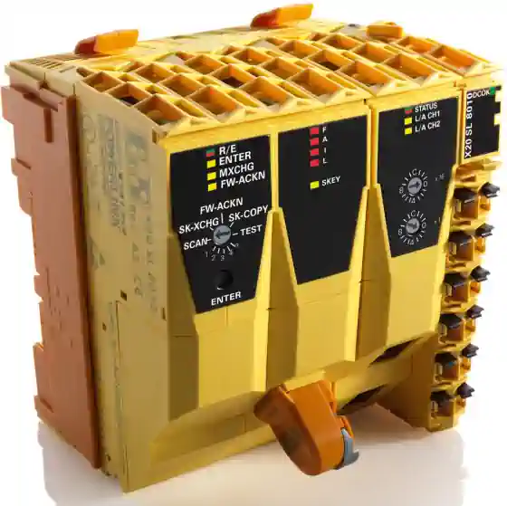
Safety PLC in CO2 Extraction Machines

PLC de seguridad en máquinas de extracción con CO2.

We use ABB B&R safety PLCs in our systems.

Safety is our mission.

It’s essential to protect people, machines and our future. To check the critical points of the system, we need a “certified safe” electronic circuit, which cannot fail when a potentially dangerous situation occurs. This circuit is called “Safe PLC”.

A safety PLC in CO2 extraction machines is built, tested and certified to meet international safety standards. The main objective of a safety PLC is the redundancy of the on-board devices. These devices are continuously monitored by a watchdog circuit. Today’s safety technology actively supports a machine’s  functionality while simultaneously safeguarding it against hazards. It adapts to changing configurations and works reliably anywhere in the world.

“A safety PLC is safe” when it has a certain level of reliability/probability of failure upon demand that can be proven/documented diagnostic coverage that detects various aspects of hardware status, program execution and operating system status.” (Roy Tanner, ABB)

Machine Directive compliance for Safety PLC in CO2 Extraction Machines.

To increase safety for machinery and workers, we design or extraction, fractionation micronization and chromatography systems following the European Machine Directive. Also if not obligatory in North America, this design approach aims at the machinery safety and at the protection of workers using such machinery. It defines essential health and safety requirements of general application, supplemented by a number of more specific requirements for certain categories of machinery.

Machinery must be designed and constructed so that it is fitted for its function, and can be operated, adjusted and maintained without putting persons at risk when these operations are carried out under the conditions foreseen but also taking into account any reasonably foreseeable misuse thereof.

The manufacturer also ensure that a risk assessment is carried out for the machinery which he wishes to place on the market. For this purpose, he should determine which are the essential requirements applicable to his machinery and in respect of which he must take measures.

The machinery must then be designed and constructed taking into account the results of the risk assessment.

PLC de seguridad en máquinas de extracción con CO2.

PED – Pressure Equipment Directive

PED - Directiva sobre equipos a presión.

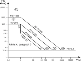
PED, (2014/68/EU) applies to the design, manufacture and conformity assessment of stationary pressure equipment with a maximum allowable pressure greater than 0,5 bar. The directive entered into force on 20 July 2016.

The Pressure Equipment Directive aims to guarantee free movement of the products in its scope while ensuring a high level of safety.

The implementation of the Directive is supported by a set of PED Guidelines and guidance documents:

  • Guidelines – pressure equipment directive 97/23/EC (related to the former PED)
  • Guidelines – pressure equipment directive 2014/68/EU

These guidelines are not legally binding – instead, they help to ensure that the directive is applied consistently. Unless otherwise indicated, they represent the unanimous opinion of the Working Group Pressure composed of representatives of the national authorities of the Member States.

  • Guidance on content of EAM drafts (PE-01-01 latest revision) (56 kB)
  • Guidance on content of PMA (PE 03-28 latest revision) (93 kB)

The list of references of harmonised standards is published in the Official Journal of the European Union.

The list of references of European Approvals for Materials is published in the Official Journal of the European Union.

Source: European Commission, Pressure Equipment Directive (PED) (2014/68/EU

.

¿Qué es una bomba de membrana?

¿Qué es una bomba de membrana?

Separeco doesn’t use piston pumps or compressors in its systems, but diaphragm metering pumps only.

Although the cost is higher if this kind of pump is compared to a simple gas booster or piston pump, the advanteges are really considerabile.

In fact, diaphragm metering pumps are not affected by supercritical fluid because process fluids are completely separated from the mechanical part of the pump. Diaphragm metering pumps meet the highest requirements and demands of the chemistry, cosmetics, pharmaceutical and biotechnology industries, or food and beverage industries. Some of most important advantages are:

  • High energy-efficiency ratio,
  • Low maintenance costs,
  • Extremely long service life for diaphragms.


Membrane Pump

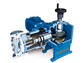
Whether navigating rough seas offshore or operating in the pristine environments of pharmaceutical cleanrooms, the global success of the ecoflow diaphragm metering pump is a testament to its reliability and cost-effectiveness across diverse industries.
Boasting precise metering rates and exceptional durability in the face of extreme operating conditions, this versatile pump offers low life cycle costs and impressive energy efficiency. A true all-around talent for various applications.

Absolutely safe startup
Initiating the metering pump is both safe and straightforward: In its non-operational state, a spring ensures the diaphragm is consistently pulled into a secure position. This guarantees maximum safety during system startup and extends the diaphragm’s service life significantly.

Low maintenance costs and a long service life
Lewa pumps are renowned for their extended service life across all components, coupled with exceptionally low maintenance and operating costs. By adhering to regular maintenance intervals, our diaphragm pumps can reliably operate for 40 years or more within your production process.

Safety and reliability in extreme operating states
At the core of our values is a commitment to safety and reliability. Our pump is engineered to withstand operating errors and extreme conditions without sustaining damage. With built-in safety mechanisms, we prioritize maximum protection for both users and machines. This safeguard extends not only to instances of excess primary pressure but also when pressure or suction lines are closed.

Membrane Pump: how it works

A membrane pump, also known as a diaphragm pump, is a type of positive displacement pump. It operates by using the reciprocating action of a flexible diaphragm, usually made of rubber, thermoplastic, teflon or metal. Here’s a step-by-step explanation of how it works:

  1. Suction Stroke: During the downward stroke of the diaphragm, the volume of the pump chamber increases. This decrease in pressure draws liquid or gas into the chamber.
  2. Discharge Stroke: The diaphragm then moves upward, decreasing the volume of the pump chamber. This increase in pressure forces the previously drawn fluid out.
  3. The cycle repeats as the diaphragm moves up again, drawing more fluid into the chamber.

The diaphragm serves a critical function as it acts as a dynamic seal between the liquid or gas being pumped and the pump drive, as well as the environment. This minimizes leakage and makes membrane pumps ideal for handling corrosive, abrasive, or sensitive fluids.

In addition to this, membrane pumps do not rely on other mechanical parts that come into contact with the transferred media except for the valves. They use the diaphragm’s upward and downward stroke action to draw and discharge liquid or gas.

Depending on pressure, membrane pump could be made of PTFE or metal. In each case, the membrane is generally double, to intercept the presence of pressure between the membrane sandwich, indicating a rupture.

Sandwich diaphragm
Sandwich diaphragm is not only extremely durable, but also well-protected. The DPS diaphragm protection system and a diaphragm monitoring system allow us to ensure that the diaphragm does not tear during operation and that the pump fluid is not contaminated.

Hermetically sealed
Diaphragm pumps work without dynamic seals in the process fluid area. This forms a hermetically sealed working area. No emissions escape to the outside, and contamination of the fluid is impossible.

Suitable for virtually all fluids
The ecoflow series is suitable for almost all liquids thanks to its flexible design. Whether they are dangerous, toxic, abrasive, viscous, environmentally harmful or sensitive fluids, the user-specific configuration always gives you the correct diaphragm metering pump.

¿Qué es un separador ciclónico?

¿Qué es un separador ciclónico?

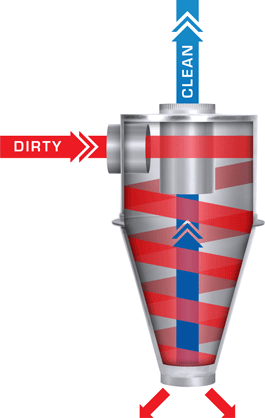
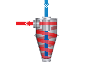
This kind of separator is different compared to the gravimetric separator, while S1 works by gravity force, S2 works by centrifugal force. The fluid moves very quickly creating a vortex inside the vessel. The fluid continues to spin and the particles of extract begin to separate moving toward the walls of the separator, sliding to bottom. This separator applies the Cyclonic Effect to separate fractions.The flow creates a cyclone inside this separator and all the compounds in the fluid are condensed along the internal walls of the vessel. The temperature of the walls determines which compound will be condensed.

With this operation, we can obtain the lighter solutes, and clean up the CO2. Our machines are equipped with 2 cyclonic separators, which are separator 2 (S2) and 3 (S3), because the first one (S1) is the gravimetric separator. S2 and S3 has got one important difference:

Separator 2 is heated, therefore the condensation point is high and light lipid-soluble compounds are collected here.

Separator 3 is cooled, therefore the condensation point is very low and water and light water-soluble compounds are collected here

What is a Gravimetric Separator

¿Qué es un separador gravimétrico?

This is the first Separator (S1). It applies the gravimetric effect to separate the extract in fractions. This separator is heated at set-point temperature.

When the mixture of CO2 and chemical compounds extracted are directed in this separation, the solvent’s temperature and pressure goes down thanks to a particular valve, which is called “Lamination Valve“. With this operation, the supercritical CO2 becomes a gas and it loses its solvent properties and so it releases the solutes that, for the gravity’s effect, fall down, in the bottom of the separator, ready to be collected.

In this separator the operator will collect all the heavier compounds, but to remove the lower compounds, water included, other operations of separation have to be conducted, with other separators.

How gravimetric separator works

A gravimetric separator is an industrial unit used to separate components based on their specific weight, size and thickness

Principle of Separation
In a gravimetric separator, gravity serves as the primary force for separation. It is practical when dealing with either a suspension (a mixture of solid particles in a gas or liquid) or a dry granular mixture.
The key idea is that the components of the mixture have different specific weights. The separator operates within a fluidizing and classification chamber where a fluid flow is employed.
Material is introduced into the fluidizing chamber from the top and gently settles in the lower section.
An fluid flow, injected into the distribution chamber, fluidizes the particles and classifies them based on the principle of gravity.
Particles suitable for production are brought into the upper section of the chamber and conveyed to the cyclone unit, while rejected material is conveyed outwards.

Specific Weight-Based Splitting
The pressurized flow enables the material to split according to its specific weight.
Heavier particles tend to travel to the higher level on the deck.
Lighter particles, on the other hand, move to the lower level.

Applications

Gravimetric separators find applications in various industries:

  • Agriculture: They are used to remove impurities, insect damage, and immature kernels from grains like wheat, barley, oilseed rape, peas, and cocoa beans
  • Food Processing: These separators standardize coffee beans, peanuts, corn, rice, and other food grains.             
  • Mineral Processing: They can separate ores from supporting rocks based on differences in specific weight.
  • Clarification/Thickening: Gravimetric separation is also used for separating fluid from solid particles.

Advantages of gravimetric separators

  1. Versatility: gravimetric separators are custom-designed based on the specific features of the processed material. This adaptability ensures efficient performance across different applications.
  2. Preservation of Particle Shape: the geometric shape of particles is maintained during the separation process. This is crucial for maintaining the quality of the separated materials.
  3. Efficient Cleaning: gravimetric separators exhibit extraordinary cleaning efficiency. They effectively remove unwanted particles and pollutants from the material stream.
  4. Low Maintenance: these separators require minimal maintenance. There is no wear in the machinery placed after the gravimetric separator, thanks to the removal of abrasive particles from the flow.
  5. No Wear: The device operates without significant wear.
  6. Easy Regulation: Users can adjust its settings easily
  7. Energy Efficiency: gravimetric separators operate with low energy consumption, making them a sustainable choice for particle classification.

In summary, gravimetric separators are cost-effective, environmentally friendly, and versatile tools that rely on gravity to efficiently separate components with varying specific weights. 
In the case of gravimetric separators applied to supercritical fluid technology, it is possible to maintain the supercritical condition rather than gaseous, to increase the separation selectivity. Our separators can operate up to a pressure of 250 bar, only on request, or in standard models up to 170 bar. All our gravimetric separators are temperature controlled.

CO2 Level – Find the equilibrium points

Nivel de CO2 - Hallar puntos de equilibrio.

We say that a liquid is in equilibrium with its gas when the same mass is exchanged from the gas to liquid and from liquid to gas. This happens continuously, and this point id strongly dependent on pressure and temperature. The change in temperature produces a change in the pressure, because, when high, more liquid CO2 turns in gas increasing pressure and when low more gaseous CO2 turns in liquid decreasing the pressure.

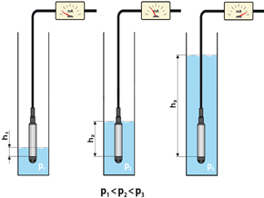
The pressure cannot give any information about the liquid CO2 level in the reservoir, but the pressure in a CO2 tank will be the same in the range from 0.1& to 100% of the liquid level inside! Therefore, a liquid level sensor is necessary to control the level. But the level is strongly dependent on the pressure and temperature inside the tank. So, to have a good control on the CO2 liquid level is mandatory to have a temperature control in the CO2 tank.

There are many point we can find the equilibrium points between gaseous CO2 and liquid CO2. All these point are situated along the CO2 Equilibrium curve. Choosing the best point is part of the system designing procedure, because it define the level of the liquid CO2 in the reservoir. As the CO2 condensing temperature at CO2 bottle pressure is about 14° C (57° F) , we chose this value to control the pressure in the reservoir. The control is fully automatic.

Caudalímetro Coriolis

Caudalímetro Coriolis

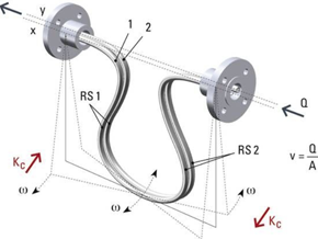
The Corilolis flow meter is basically a mass flow meter. It gives you exactly the mass of CO2 is delivered by the membrane pump, with at least three advantages if compared to traditional meters:

It has no moving parts. It works at full pressure at the outlet of the pump without compromising the suction flow or producing cavitation. It works with all the fluids status, gas, supercritical, liquid.

Because of its high pressure, no traditional meters are available for supercritical CO2. Of course this high performance technology is not cheap. Many system are not equipped with any flow meter to be more competitive in the price, but in this way, you will never be sure about how much and if the CO2 is really flowing in the circuit. Maybe is the expected flow or maybe nothing! Who can say it. Impossible to be sure. The Coriolis flow meter is essential to have the correct feedback and control the CO2 flow in the circuit. The full automation system detects the feedback from the flow meter and drive the motor to give exactly the expected kg/hr. This is irrelevant. As you can see in the pomp flow topic, lower and higher flow give less extract than optimal.

Recycling – CO2 Condenser

Reciclaje - Condensador de CO2.

The condenser is essential in CO2 recirculation. The condenser is a piece of apparatus or equipment that can be used to condense, that is, to change the physical state of a substance from its gaseous to its liquid state. We use double pipe configuration in small systems (up to 48 liter) and shell and pipe configuration for industrial. We do not use plate exchanger as they clog easily and cannot resist to standard CO2 pressure.

The condenser is an important part of the extraction system as, without it, it cannot be possible to recirculate the CO2.


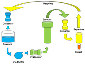
In fact, all along the process, CO2 continuously changes its status: first liquid, then supercritical, then gaseous and finally back liquid again. Here on the right see all the changes, step by step. Colors: Blue = Liquid CO2, Green = Supercritical CO2, Yellow = Gaseous CO2.


When the gaseous CO2 comes out from the separators, the CO2 is completely clean and can travel to the condenser and, after that, to the Reservoir, where the Liquid CO2 is stored, waiting to be pumped again in the circuit.

Quick closing system

Sistema de cierre rápido.

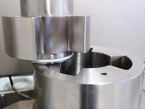
Quick opening cover design needs only one-eighth of a turn rotation for sealing. Ideal for high pressure operations requiring repetitive opening/closing. The “Clover Leaf” Closure Reactors provide maximum ease for quick opening or closing of the cover. The cover is simply inserted into the body and then rotated one-eighth of a turn. A safety locking pin is provided to insure that the cover is properly positioned and locked. One of the most difficult aspect is attaining continuous feed of the solids and continuous discharge at high pressure extraction vessels. Generally, the solid feed material is handled by using preloaded canisters. A quick opening closure that allows for rapid opening and closing is essential. Bolt closure is not safe and it takes a lot of time to open. On the other hand, cloverleaf cover opens in one second. If considered under the safety point of view, the cloverleaf cover offers three safety systems operating at the same time:

The static pin. When the lid is in close position the operator introduces the safety pin in the vessel hole. Remove the pin to rotate the lid.

The dynamic pin. When the pressure build up in the vessel, the cover moves up and the dynamic pin goes in the safety hole in the cloverleaf upper side. When the pressure is completely removed, the lid will go down clearing the dynamic pin. Now the lid can rotate to open.

The electronic sensors control the correct position of the lid. If the sensors are not perfectly aligned, the process cannot start.